Sensing and Valving
Pressure Sensing
Since we only need an over-pressure/under-pressure alarm here, we have identified two possible options for pressure sensing. Option 1 describes using an off-the-shelf piezoelectric pressure transducer. Option 2 describes a simple U-Tube manometer that is low-cost and less dependent on supply chain restrictions. Either option will provide pressure readout in real-time and trigger an alarm when the pressure is under about 5 cm H20 or over about 40 cm H20. These preset thresholds are constant for all patients in the current system setup. These alarms are only meant to signal catastrophic failure, and thus hospital personnel should be monitoring the pressure readout at all times. The two options are detailed below.
Build 1: MPX Pressure Transducer
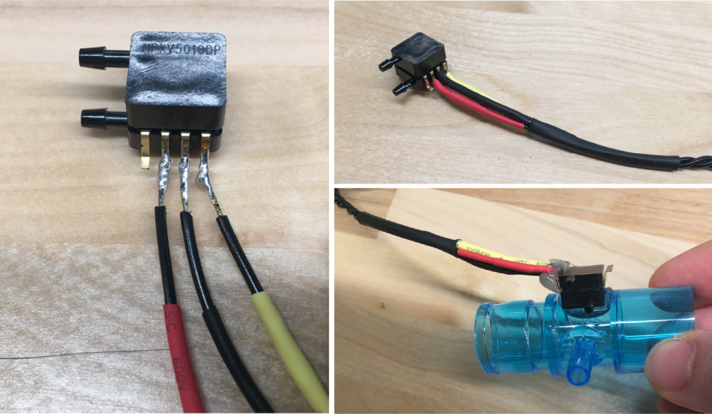
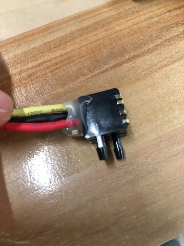
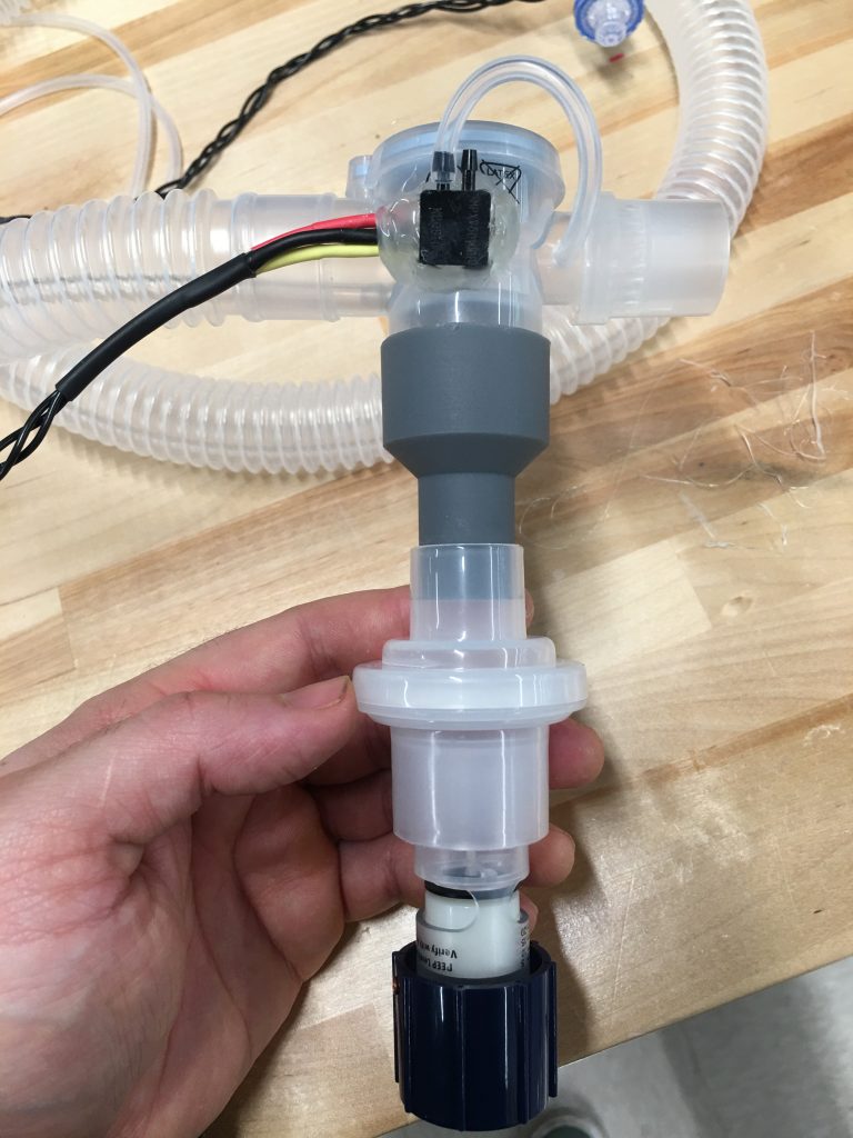
Using a commercial MPX Pressure Transducer: This sensor produces an analog 5V signal output that can be acted on in software to trigger alarms in the event of over-pressurization or a loss in pressure. Note: there are breakout boards for this 8SOP chip style, but the sensors can also just be directly soldered using just 3 connections, and reinforced with hot glue. This sensor is a relatively low-cost pressure sensor (currently in relatively good supply) that takes 5V and Ground, with an analog output voltage from 0V-5V, indicating the pressure throughout the pressure transducer’s range. A few different sensors are suitable for the pressure range that needs to be sensed. In the following walk-through, we use the 10kPa range MPX5010DP pressure sensor.
Materials
- MPX Pressure Transducer Options:
- MPXV7007DP Pressure Transducer (7kpa range)
- MPXV5010DP Pressure Transducer (10kpa range)
- MPXV5010GC7U Pressure Transducer (10kpa)
- MPXV7007GP Pressure Transducer (7kpa)
- MPXV5010GC6U Pressure Transducer (10kpa)
- 24 Gauge 3-Conduit Wire
- Heat Shrink
- Wire Stripper
- Soldering Iron & Solder
- Hot Glue & Gun
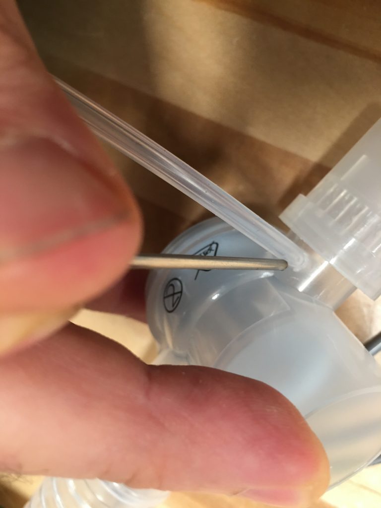
- 2mm ID x 4mm OD Silicone Tubing
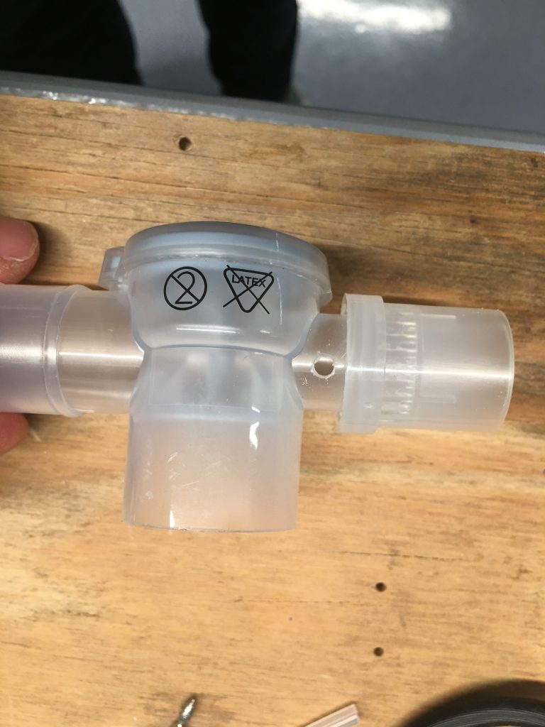
- Ambu blue T-junction connector piece (in Ambu kit)
Build 2: U-Tube Manometer
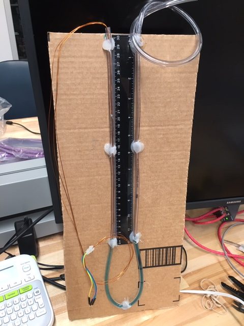
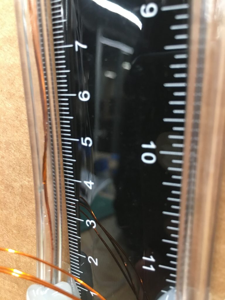
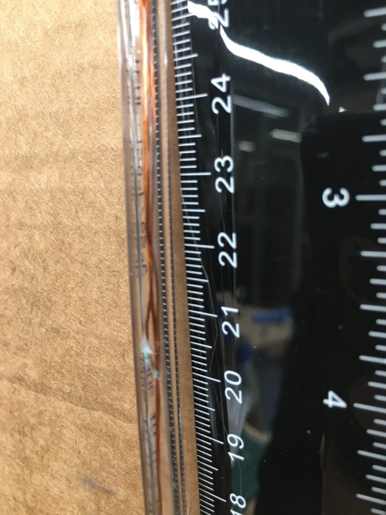
We can alternatively create a U-tube manometer out of IV tubing. The pressure is given by the difference in height between the two columns of water multiplied by two. One side of the tube is hooked up to the output of the bag valve system, and the other side is open to the environment.
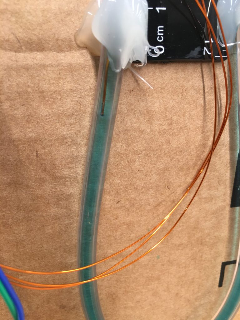
To make it a little smarter, we install a set of wire leads into the manometer to detect over/under pressure, using the fluid in the manometer to conduct the signal. We were inspired by this video and fabricated a very basic pressure sensing setup that consists of constant cross section clear tubing, a ruler, two transistors, two resistors, and three pieces of wire.
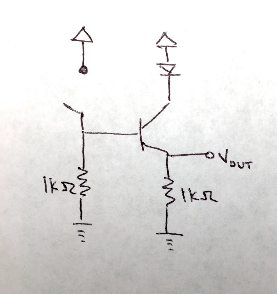
The circuit on the left is the basic building block for each of the sensing leads. The way the circuit works is the following: the 5V+ line is treated as COMMON and placed at the bottom of the U-tube. For bot the low and high pressure sensing leads, when either of them comes into contact with the fluid in the manometer, we sense this as connecting the “switch” (i.e. the high/low pressure lead and the common wire). The fluid acts as a conductor to close the circuit. This sensing signal is fed into the base (gate) of the NPN BJT transistor, and when connected to COMMON, it turns the transistor on, lighting up the LED, as well as producing a voltage V_out that can be scoped with a microcontroller to act on in software. The signal produced at V_out is 5V minus the voltage drop across the LED. Alternatively, a buzzer can be placed as the load, or inline with the LED to act as an alarm. Note that the HIGH PRESSURE signal is normally when the LED is OFF, and will only alarm when the LED is ON, while the LOW PRESSURE signal is normally when the LED is ON, and should be triggered for alarm when the LED isOFF.
Materials
- Plastic IV Tubing (⅛ – ¼ ” ID)
- Dye (Methylene Blue – FDA-safe if it gets into lungs of patient)
- 12″ Ruler
- 25mL Syringe
- Hot Glue & Gun
- Piece of cardboard/wood
- 2 Transistors (2N3904 or similar NPN BJT)
- 2 LEDs
- 1k Resistor
- 10k Resistor
- Solderless Breadboard
- Razor Blade/Sand Paper
- Magnet Wire (30 Gauge)
Plumbing
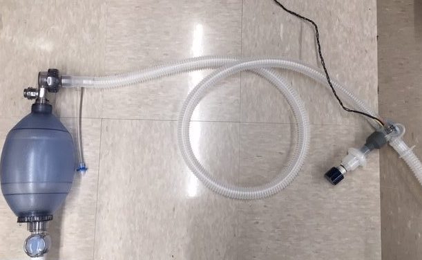
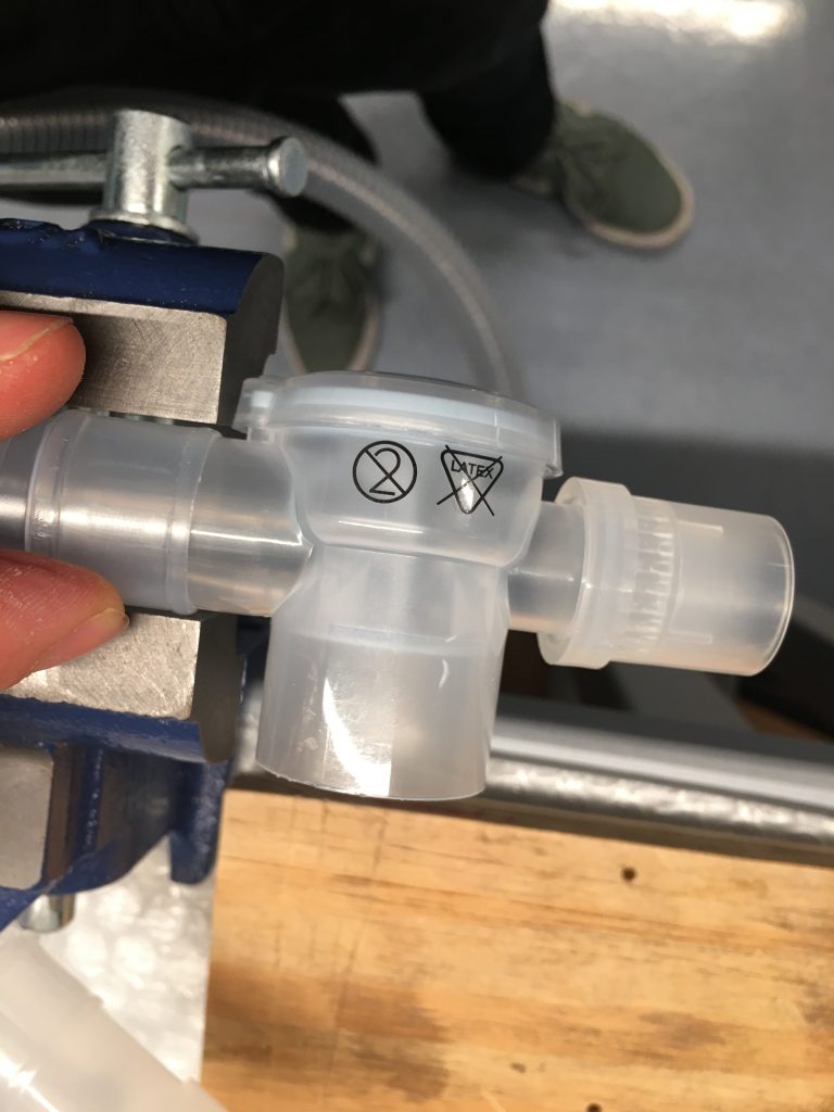
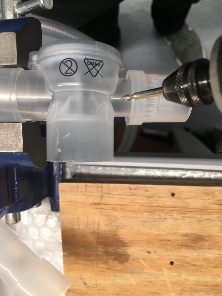
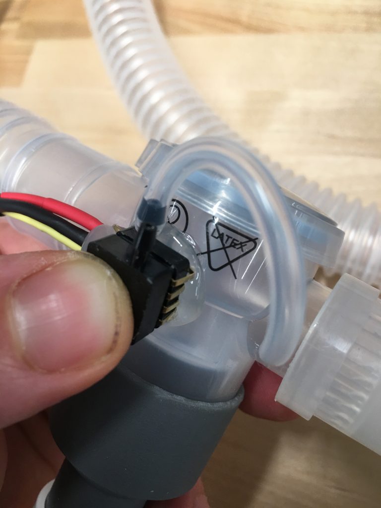
Proper plumbing of the air circuit is important in this application in order for the ventilator to operate properly. We seek to minimize the dead-space in the tubing. The dead-space is proportional to the tube length, so in connecting our pressure sensor and adapting the Ambu Bag kit to this application, we want to minimize the number of connectors and adapters that are needed to connect the system together.
Materials
- Smith Medical Single-Limb Ventilation Circuit
- Ambu Bag Kit
- Pressure Sensor Assembly