Electronics and Control
We have implemented two modes of operation. The first mode is volume-controlled (VC) ventilation mode and should only be used on patients who are chemically paralyzed. Tidal volume is set mechanically (see Mechanical), and the device is configured to deliver steady, repeatable breaths at BPM and I/E settings as determined by the physician. The second mode is BiPAP/Breath-Assist mode. In this mode, the device is configured to assist patients who are having trouble breathing on their own. The two modes are described in detail below.
Ventilation Control Scheme
The first and primary function of our device is as a positive-pressure mechanical ventilator to facilitate respiration in patients who are unable to breathe on their own. This entails being able to deliver steady, repeatable breaths for long periods of time, with breath rates ranging from 5-55 BPM, and inspiration/expiration ratios ranging from 1:1 and 1:4 (as determined by our clinical collaborators).
Breathing Cycle, Timing, and Open-Loop Control:
Windshield wiper motors run in open loop. While optical encoders could be used to close the position loop, these would add cost and complexity to the system. To rectify this, we have implemented a pseudo-closed-loop paradigm, wherein we sense the position of the motor at the two most important points in the respiratory cycle (full inspiration and full expiration). Once we know these positions, we assume that the motor speed is constant between these two positions for a fixed voltage (which is a good assumption so long as the motor has sufficient torque to reject disturbances presented by the Ambu® bag’s compression sequence and the back pressure generated from the lung inflation process). Therefore, if we know exactly when the motor was at full inspiration/expiration, and we assume a constant speed in between, we have a good idea of the motor’s position within the breathing cycle at any time. Further, this scheme allows us to sense absolute position at these locations, meaning we do not need to worry about position drift over time due to missed encoder counts.
To realize this motion control scheme, we have two limit switches at the extremes of travel which are mechanically triggered when the ventilator is at full inspiration and full expiration. In a single breathing cycle, the motor is driven at a constant speed (inspiration speed) to compress the Ambu® bag until the inspiration limit switch is tripped (the inspiration cycle). Once this switch is triggered, the actuator is driven backwards at a different speed (expiration speed) to relieve pressure in the Ambu® bag until the expiration limit switch is tripped (the expiration cycle). The ratio of inspiration to expiration speed comprises the I/E ratio. The sum of the inspiration and expiration cycle times equate to a full breathing cycle. The actual inspiration and expiration cycles are recorded, and the motor speed is adjusted if need be. The physician may adjust both the breathing rate and the I/E ratio independently via two potentiometers, as described in the following section.
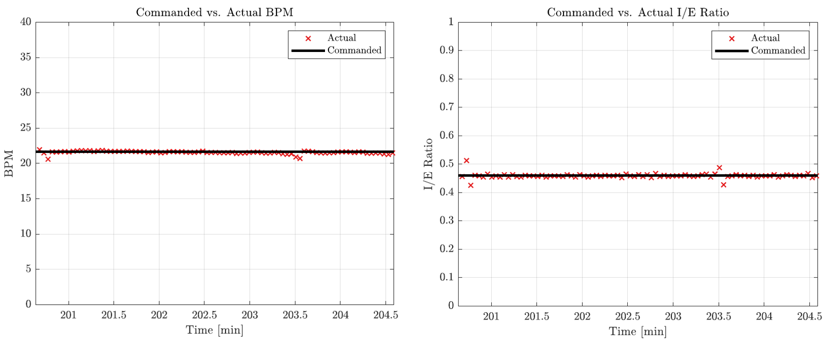
The consistency of our open-loop control paradigm is demonstrated in the following figure, which shows the commanded vs. actual BPM and IE recorded during our 4-hour live swine experiment.
BPM and I/E Ratio Programming:
The physician can program a new BPM and I/E ratio by holding down the ‘Program’ push-button and simultaneously turning the respective potentiometer knob. It should be noted that turning the potentiometer knobs without holding down the ‘Program’ button does nothing; this is to minimize the possibility of inadvertent cycle modifications. Once the ‘Program’ push-button is released, the breathing cycle is instantaneously updated to reflect these new parameters (by adjusting the duty cycle of the PWM signals sent to the motor), and the new BPM and I/E settings are stored in non-volatile memory (EEPROM) on the MCU in the form of a 8-bit integer. In the event of a power cycle, the ventilator program always recalls the BPM and I/E settings stored in EEPROM from the previous operation, and initialize the breathing cycle using the stored settings.
Continuous Mode: This mode is activated when the chosen BPM/IE settings result in reliable (linear) speeds for the motor that are comfortably above the motor’s deadband. In this mode, the ventilator undergoes continuous motion in both inspiration and expiration cycles. This mode is encountered for high BPM (>20) and IE (1:2 or higher).
Discontinuous Mode: It is possible to select a BPM/IE configuration that results in speeds that are too low for the motor to handle. For example, a low BPM (<20) with a low I/E ratio (1:4). In this scenario, the expiration speed commanded is in the motor’s deadband. To remedy this, a discontinuous motion profile is implemented where, on the expiration cycle, the motor pauses at full expiration for the amount of time needed to realize the BPM/IE settings, after which, normal motion is resumed.
Plateau Pressure
To measure plateau pressure, the physician presses and holds the ‘Inspiration Hold’ button, which causes the ventilator to pause and hold at the next full inspiration event (i.e. travel until the inspiration limit switch is triggered, and then stop). This gives the physician time to read the plateau pressure which is displayed on the LCD screen. Releasing the ‘Inspiration Hold’ button once more causes the ventilator to resume a normal breathing cycle. It should be noted that simply pressing and releasing the ‘Inspiration Hold’ button will NOT result in an inspiration hold event, and the normal breathing cycle will continue. This is to minimize the possibility of inadvertent inspiration hold triggering without release, which could happen if a physician accidentally presses the button and walks away. This event would be catastrophic to the patient. Thus, a hold-and-release method requires the physician to be physically near the patient and ventilator during the entire cycle hold process.
Enable/Homing
When the system is initially powered on, it is in a ‘Standby’ state (i.e. not moving). Flipping the ‘Enable’ rocker switch into an ‘on’ position puts the ventilator into a normal respiratory cycle state, and the direction of travel (inspiration or expiration) is read from EEPROM based on the last known travel direction. Flipping the ‘Enable’ switch into an ‘off’ position causes the ventilator to ‘home’, wherein the ventilator travels to full expiration, stops, and enters a ‘Standby’ state. This function was implemented to allow the physician to remove the Ambu® bag from the ventilator and take over with manual resuscitation if need be.
BiPAP Control Scheme
Through consultation with our clinical collaborators at VUMC, it became clear that implementing BiPAP (Bilevel Positive Airway Pressure) capabilities could potentially open up our device for use with less at-risk patients who simply need breathing assistance, thereby freeing up clinically-approved ventilators for those who are most at risk. This would also alleviate the requirement for patient to be chemically paralyzed. In BiPAP mode, our device simply monitors the pressure sensor, and as soon as the pressure reading goes negative (indicating an attempt by the patient to inspirate), the device triggers an inspiration assist maneuver to compress the Ambu® bag and deliver air to the patient. The tidal volume of air delivered is set by the physician. However, the system also monitors inspiratory pressure, and if this pressure exceeds a barotraumatic limit (40 cm H20), the direction of travel is immediately reversed and the cycle enters the expiratory state while sounding an alarm.
Electronics Fabrication
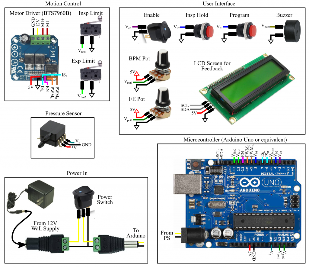
The wiring diagram for the control electronics is shown below. The system is powered by a 12VDC, 3A wall transformer, coupled to the Arduino’s input barrel jack through a power switch. The Arduino Uno MCU (or equivalent) is responsible for executing the controller, processing sensor/user interface data, and issuing motor commands. Various user interface features (potentiometers, buttons, switches, and an LCD screen) allow the physician to interact with the ventilator and monitor the patient. The LCD screen displays the current BPM and I/E settings, and provides a real-time reading of the output pressure as measured by A MEMS pressure sensor (assuming Option 1 from Pressure Sensing is used). An alarm is sounded (via a piezoelectric buzzer) if the pressure rises above or falls below pre-defined pressure limits. To actuate the motor, the MCU sends PWM signals to a high-power motor driver circuit (based on the BTS7960B half-bridge driver) which sources the voltage (12V) and the current (>2A) that the motor requires. All logic inputs (switches and pushbuttons) short their respective digital pins to ground when pressed, relying on the Arduino’s built-in pull-up resistors which are activated in software, to minimize the overall number of external components. The LCD screen is updated every 1000 control cycles via I2C protocol.
Electronics and Component Wiring
To create the necessary control electronics components, you will need the following materials.
- Arduino Uno (or equivalent)
- Potentiometers (10k) (x2)
- Limit Switches (x2)
- Momentary Pushbutton (Off-Mom)
- Power Switch (rocker variety)
- Enable switch (rocker variety)
- Motor Driver (BTS7960B)
- LCD Display for Feedback (with i2c backpack)
- Piezoelectric Buzzer (5-12V)
- DC Barrel Jack with Screw Terminal (Male)
- DC Barrel Jack with Screw Terminal (Female)
- 12V, 5A Power Supply
- 20-22AWG Speaker Wire
- Various Jumper Wires (24AWG) and Heat-Shrink Tubing
- Solderless Breadboard or CoV Shield (see below)
- Spiral Cable Wrap
- Adhesive-Backed Cable Brackets
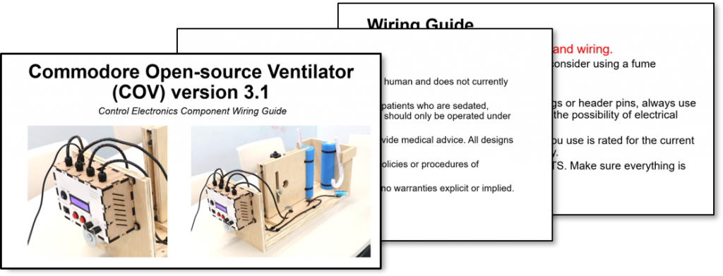
Click the image below to download a comprehensive component wiring guide for the CoV:
Control Enclosure Fabrication
To fabricate and assemble the CoV control electronics enclosure, you will need the following materials.
- Laser-cut enclosure panels (dxf files downloadable here)
- (4x) No.2, ¼” long brass wood screw (McMaster: 98685A220)
- (4x) No. 4, 1-1/4” long slotted flat head screw (McMaster: 90006A117)
- (4x) Nylon unthreaded spacer, 3/16” OD, 0.115” ID, 1” long (McMaster: 90176A125)
- (4x) M12 panel-mounted cable glands, cable diameter 3mm-6mm
- (14x) 4-40, ½” long machine screws (McMaster: 90272A110)
- (14x) Size 3, ½” long slotted wood screw (McMaster: 92407A096)
- (14x) 4-40 square nut (McMaster: 94855A281)
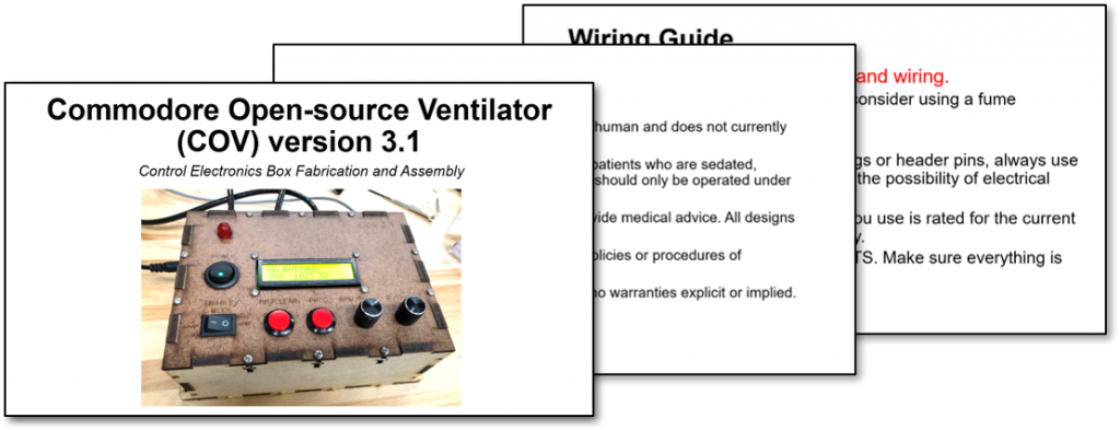
Click the image below to download a comprehensive fabrication and assembly guide for the CoV control electronics enclosure:
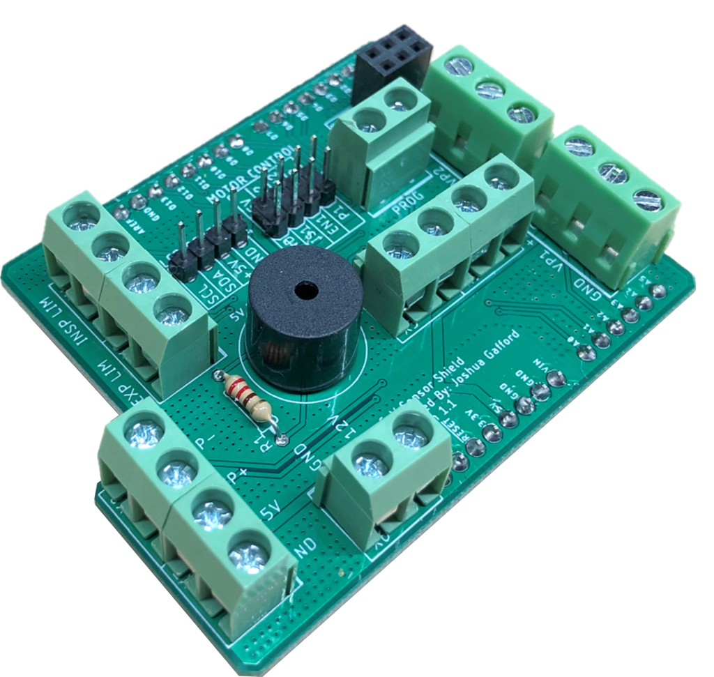
The CoV Uno Shield
To simplify wiring and minimize the amount of soldering to be done, we have designed a custom stackable shield for the Arduino UNO that breaks out the necessary connections into screw terminals and pin headers for easy interfacing. It also includes through-holes for a piezo buzzer which is driven with one of the PWM pins. Click the image below to download the Gerber files (they can also be downloaded on the Downloads page). NOTE: This is OPTIONAL. The control electronics connections can still be made without it using a solderless breadboard or a protoboard.
Final Control Enclosure Assembly
The enclosure for CoV version 3.1 is shown below:
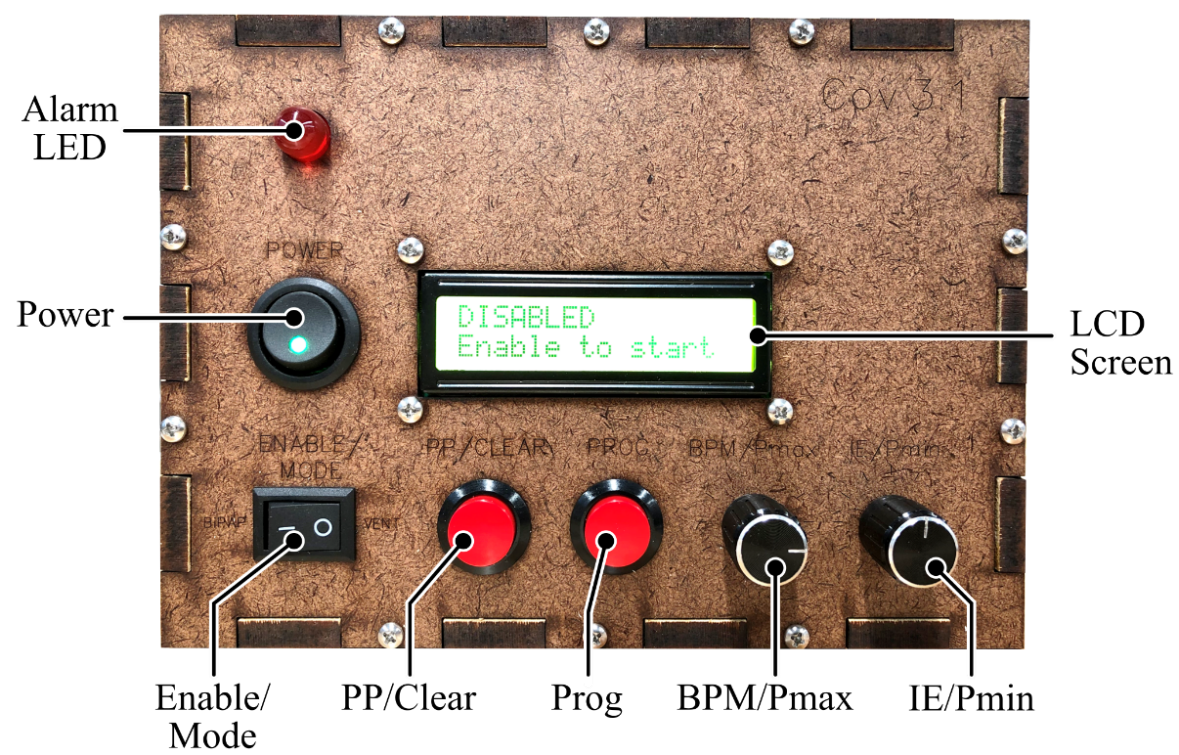
- POWER switch: this switch provides power to the motor and the on-board computer. This switch functions as the device’s emergency-stop switch.
- Alarm LED: this LED blinks when an alarm state is encountered. It is accompanied by an audible tone.
- ENABLE/MODE switch: Before startup, the state of this switch determines whether or not the device boots up in Ventilation mode or BiPAP/Breath Assist mode. When powered on, this switch toggles between ‘NORMAL’ and ‘DISABLED’ states.
- PP/CLEAR button: This button serves three functions:
- When the device is in PROGRAMMING mode, this button loads the current settings into memory and exits PROGRAMMING mode.
- When an alarm is encountered, this button acknowledges and clears the alarm.
- When in NORMAL ventilation mode, this button can be used to perform an inspiratory hold for plateau pressure measurement.
- PROG button: This button toggles between pressure threshold programming, and respiratory parameter (BPM and I/E) programming.
- BPM/Pmax knob: In Ventilation mode, this knob is used to adjust the BPM or maximum pressure threshold settings. In BiPAP mode, this knob is used to adjust the maximum pressure to trigger an expiratory transition.
- IE/Pmin knob: In Ventilation mode, this knob is used to adjust the I/E ratio or minimum pressure threshold settings. In BiPAP mode, this knob is used to adjust the length of the patient timeout alarm.
- LCD Screen: This screen informs the user of the current status of the device, relevant device and patient parameters, and prints any alarms.
Software
The software is written in the Arduino environment, using a language derivative of C/C++. The Arduino IDE can be downloaded from here. After downloading the IDE, you may upload our code on an Arduino-compatible MCU. We have provided the link to a github repository for the controller code on the Downloads page. Note that the software has only been tested on the Arduino UNO model which implements the Atmega328 MCU, and with the BTS7960B motor driver. We cannot guarantee proper operation on any other MCU/motor driver combination.